When a stamping die gives out, manufacturing stops – an interruption that major car companies cannot afford to let happen.
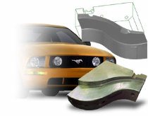
That’s why Ford turned to Detail Technologies to reverse-engineer two Mustang stamping dies that were nearing the end of their life span.
Detail Technologies builds original and duplicate plastic injection molds, stamping dies, compression molds, and individual components.
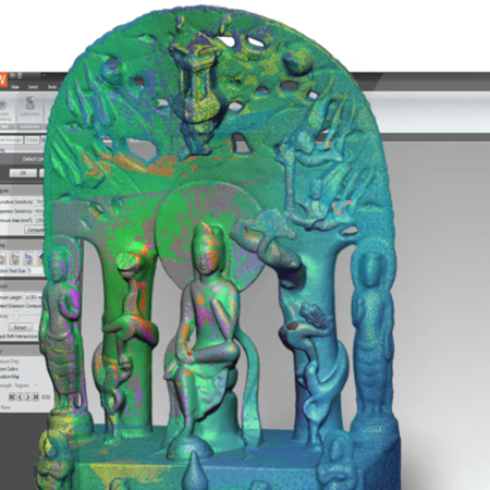
The company relies on Geomagic Wrap software, which automatically converts point clouds from a scanned physical part into accurate digital models for downstream CAD/CAM and machining.
Most often, tool steels that come to Detail Technologies were originally cut to CAD data, then altered by hand to accurately form the parts. That fine-tuning makes duplication a challenge.
“Stamping steel is not an exact science, and steels are almost always altered from design intent,” says John Amos, a reverse-engineering specialist at Detail Technologies. Eventually these steels need to be repaired, replaced or copied.
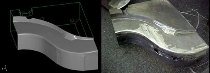
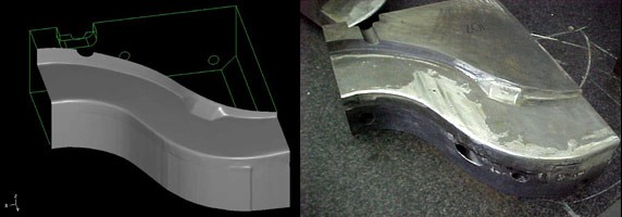
The scanned steels and the matching 3D data created in Geomagic Wrap.
“Unless a customer with great vision obtained the data for future reference,” says Amos, “there is typically no way to reproduce steels without going through the same tedious process.”
That was the position Ford found itself in when the steel tools for stamping and restriking a Mustang cross-member – a part of the frame that attaches the rails – reached the end of their lifecycles. Rather than invest $400 million to retool a Mustang model still on the market, Ford opted to tack on a few more good years by finding someone to rebuild the aging tools before they officially fell out of commission.
Re-building to avoid re-tooling
“Die” is a generic term used to describe the tooling that produces stamped parts. A die set consists of two opposing components that first form, and then punch, holes in steel. The upper half of the die set is mounted on a press ram and delivers the stroke action; the lower half is attached to an intermediate bolster plate, which in turn is secured to the press bed. Guide pins are used to ensure alignment between the upper and lower halves.
Generally, the tools have a projected lifespan of between eight and 12 years.
“Stuff wears down,” says Amos, "and anyone who has seen how stamping works knows that the process is abusive to tools.”
Life expectancy for tools is cycle-dependant – the Ford Mustang is not a huge seller, for example, so its tools would have a longer life expectancy than those for an F-Series truck or an Escape SUV.
As long as demand for the vehicles remains, production will be extended with no change to the structural parts. With each extension, the risk for complete failure increases.
“Someone always has to have the responsibility of saying, ‘allocate the money to make these tools more reliable before we have a disaster,’” Amos says. “The Mustang tools were not broken. They could possibly have run another year or two. But the probability of failure and the cost of that failure outweighed the cost of re-building a couple of tools.”
Creating new tools from old
The two Mustang tools that Ford decided to have rebuilt are used to stamp cross-members that are about 6 feet long and 8 inches wide. Sheets of steel are laid in the first tool, stamped, then restruck with the second tool to further force the corners. A backlog of parts was created to meet requirements while the tools were taken apart, scanned and rebuilt.
Forty-two individual steels were sent to Detail Technologies – 21 per tool – each about the size of a breadbox. They were scanned with a Laser Design, Inc. RPS450 scanner, which has a data collection rate of up to 14,400 points per second. Two data collection sensors operate independently, enabling data that falls in the shadow of some other geometry on the part to be reached.
Amos scanned the steels in their first orientations with each of the two separate sensors then manipulated either the steels or the scanner into another position as needed to collect missed sections. This process was repeated until point-cloud data was collected for complete coverage.
Amos wrote down the coordinates of at least three of the orientation spheres in his final scanned file matrix, and inserted the PH10 probe head back into the CMM to measure 2D data (lines, dowels, screws) as well as the spheres themselves. That enabled a rotation matrix to be created for marrying the files together.
After final scanning, the original tools were reassembled and put back into production. Another backlog of parts was created for when it came time to disassemble and reassemble the new steels.
The final point-cloud data for the steels – each containing 3 to 4 million points – was loaded into Geomagic Wrap, where Amos set the distance sample to .005, and curvature sample to about 70 percent. He shaded the point cloud and isolated any areas that looked problematic. This reduced the point cloud to a more manageable size, while still keeping the points necessary to maintain accuracy.
“Welds on the tool surface cause pitting that will result in an ugly polygon,” Amos says. “The surfaces need to be smooth, or else the tool would show up looking welded again.”
Once rough areas were fixed, Amos continued with a surface wrap – cleaning and relaxing the data to the default settings and eliminating spikes. He isolated the holes – spots where there were voids in the data – and filled them using mathematical controls available in the software.
The resulting surface boundaries were manipulated, constrained and or unconstrained, and shuffled until Amos had a structure that would create accurate workable surfaces. He applied and surfaced grids – usually to the default settings – then created an error map to match the created surfaces with the points from which they were created.
The two data sets were saved as an IGES file and loaded into the MasterCam CAD system, along with a CMM file containing the sphere locations. Amos used the sphere location information to manipulate the two data sets into the same orientation, and extended edge surfaces that were cut off (a trim edge, for example) during the reverse-engineering process. The finalized CAD file was saved for the CAM department.
Archiving data before the fact
The CAM department used the CAD files produced from the steels of the two tools to manufacture blocks that were rough-machined, semi-finished, heat-treated and hard-milled into identical tool replacements. The finalized tools were shipped to Ford and in production after a total of five weeks – four days devoted to the scanning and modeling, the rest of the time to taking apart the tools and manufacturing. The tools were out of production for only 10 days.
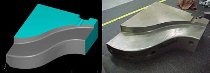
Geomagic Studio was used to create accurate workable surfaces to remake the tools
The amount of time could be reduced even more, Amos says, if manufacturers would make it standard practice to reverse-engineer tools once an approved part is created, ensuring that a digital archive is always available. When a tool approaches its breaking point, the data would be accessed, the tool recreated, and the old switched out with the new.
“We have an extensive file-server system and pride ourselves on being extremely proficient at keeping archived data,” Amos says. “But so often the reverse-engineering work I do revolves around recreating data that a customer can no longer locate. There’s generally no down time available in production tool runs, so when they need it, they need it now. It would be nice if businesses would invest in the security of having a reproducible product up front by scanning tools right after certification. The process would be much more efficient.”
当冲压模具报废的时候,生产制造会被迫停滞。汽车制造商大多无法承受这样的停滞发生。这就是为什么福特 (Ford)公司求助Detail Technologies公司对两个要达到使用寿命的野马汽车(Mustang)冲压模具实施逆向工程。
Detail Technologies生产新的和复制注塑模、冲压模、压铸模及各个部件。公司使用Geomagic Design X逆向工程软件,Geomagic能够处理三维扫描实物零件得到的点云, 自动把点云转换成精确的数字模型,以用于下游CAD/CAM/CAE系统和机械加工及分析。

通常,送到Detail Technologies公司的模具钢已经是先按CAD数据被切削,然后再通过手工精度调整制成零件。微调工序成为复制精度重复性的难题。
“冲压钢不是一门精密科学,这些钢通常与设计意图有所不同。”John Amos说,他是Detail Technologies公司的逆向工程专家。最终这些钢需要被修复,替换或复制。
“除非是极具远见的客户获得了未来参考标准的数据,”Amos说,“否则,为了复制这些冲压钢,必须经历同样单调的工作程序。”
当用于冲压和再冲压野马汽车(Mustang)横梁与框架的钢模具达到使用寿命时,福特公司发现自己现在所处的情况就如上所述。与其投资4亿美元来重新整合仍处于市场上的野马汽车型号,福特公司选择对正在老化的模具用逆向工程重建,避免正式停止使用,延长钢模具使用期多年。
重建模具避免重整汽车型号
“模具”是一个普通的术语,这个案例用它来描述制造冲压件的加工设备。一套模具组由两个相对的部件组成,它对钢先成形,再冲压和打孔。模具组的上半部分被安装在一个冲压杆上,用来传递冲压动作;下半部分被安装在中间的支承板上,用来依次闭合到冲压座上。定位销用来确保模具组上下部分的对齐。通常情况下,模具设备有一个8到12年的设计使用寿命。
“模具损耗了,”Amos说,“任何懂冲压工序的人都知道这个工序对模具损耗很大。”
模具的期望寿命依赖于工作周期。例如,福特野马汽车不是销量很大的车型,因此它的模具将比F系列卡车或Escape SUV运动型多功能车具有更长的期望寿命。
只要对车辆的需求依旧存在,对各结构件的生产就要长期不变地进行。伴随每一次生产的延续,模具完全失效的风险都在增加。
“工程师的责任在于对问题的警觉性 ‘我们在模具彻底失效前,投入资金来重建模具更可靠’,”Amos说,“野马汽车模具没有失效过,它们可能再运转一两年。但是失效的可能性和代价要远高于重新开几个模具的成本。”
用老模具创建新模具
福特公司决定重建两个野马汽车模具.用途是冲压大约长6英尺、宽8英寸的横梁构件。钢制钣金放置在第一个模具上,冲压,再用第二个模具再次冲压折弯角。在模具被卸下分离、扫描和重建时,先生产一定库存的零件来满足需求。
42个独立的模块,每组模具21个,每个模块大约面包盒大小。用LDI RPS450扫描仪采集点云,这种扫描仪数据采集率可以达到每秒14,400个点。两个数据采集传感器独立工作,以保证零件上一些几何背影特征的数据能够被采集。
Amos用两个独立的传感器在第一个坐标位置扫描了钢模具,然后移动钢模具或者扫描仪到另一个位置以采集错过的部分。不断重复这个过程直到点云数据被完全采集到。
Amos在它最终的扫描文件坐标值列表中记录下至少三个坐标球的坐标位置,并在CMM三坐标测量机上重新安装PH10测头来测量2D数据(线、销位、螺位)及坐标球本身。这样可以创建一个旋转矩阵来合并所有数据文件。
扫描结束后,老的模具被重新装配起来,继续投入生产中。用老模具再生产一定库存的零件以备将来拆卸和装配新的模具。
零件的整体点云数据(每个零件包含3到4百万个点)被导入Geomagic Wrap软件,这里Amos设置采样距离为0.005英寸,曲率采样为大约70%。他对点云数据进行着色,分离出任何看上去有问题的区域。根据工程需要减少点云数据并保持一定量的扫描点以保证精度。
“模具表面焊缝会引起凹陷,这些凹陷会导致很难看的多边形三角网格面,”Amos说,“曲面需要平滑,否则模具可能再次现露出焊缝。”
Geomagic 软件里有精确的算法,用于修复粗糙的区域。Amos继续进行曲面设计,他用Geomagic Wrap补曲面凹陷和消除钉状数据。他可以分离孔和面的区别(数据空缺的地方),并用软件里精确的算法控制来填充这些孔。
曲面的边界也需要处理、增加约束或去掉约束、移动,直到Amos完成一个精确可用的曲面。然后通过比较点云数据和创建的曲面得到一个误差色谱图,这样对曲面的精度才有把握。
两个数据集(点云和曲面)被保存为IGES文件,然后连同一个包含定位球信息的CMM文件一起导入MasterCAM CAD系统中。Amos使用球位置信息来对齐两个数据集到相同的坐标位置,并延伸在逆向工程过程中被剪切掉的边界曲面。最终完成的CAD文件被保存给CAM部门。
失效事实发生前存档数据
CAM部门利用两个模具创建的CAD文件制造出模具块,这些模具块被处理(粗加工、半成品制造、热处理、硬铣削)成相同的模具替代品。最终的模具被运送到福特公司用于生产,整个过程共5个星期,其中用来扫描和建模只有四天,其它的时间用来拆卸模具和生产。模具离开生产线只有10天时间。

Amos说,时间总量还可以再减少,如果制造商把逆向工程列入标准程序:一旦零件经核准马上就对其模具实行逆向工程,这样可以确保数字化存档数据任何时候都可以拿到。当一个模具接近它的失效点时,存档数据被取出,重建模具,老的模具立刻被新的替换。
“我们有一个庞大的文件服务器系统,能够非常专业化地保存存档数据,这使我们很自豪。”Amos说,“但是我做的逆向工程工作常常是围绕着客户找不到的数据。通常在模具运转的生产过程中根本不允许有停机时间,因此当他们需要模具时就是马上需要。如果商业界愿意投资,模具核准之后就扫描,预先得到一个可重复制造的产品,那就太好了。这个工作流程将更加高效。”